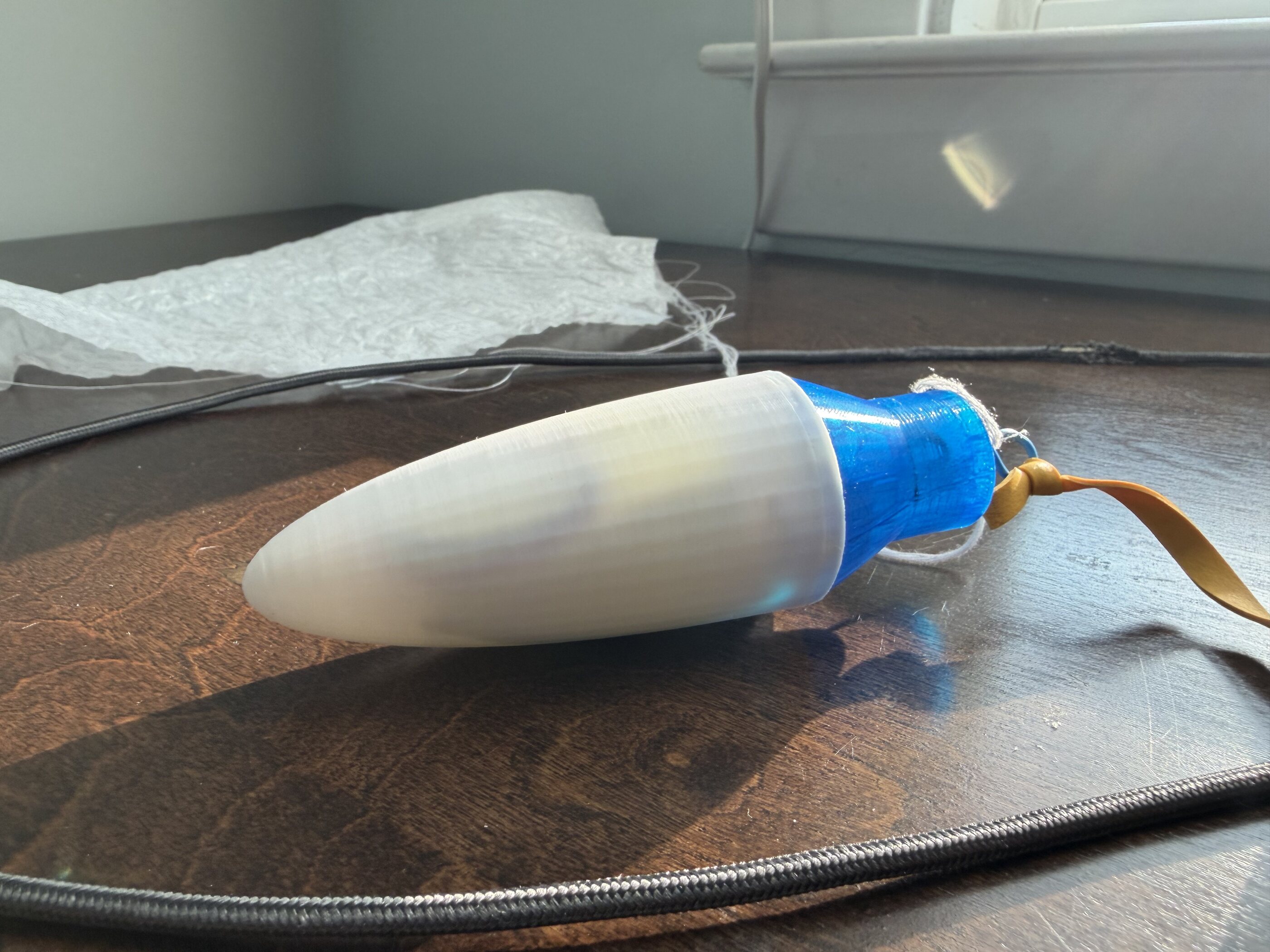
Mark-II fairing: white PLA nose cone on blue TPU base adapter, parachute laid out behind it

Scratch-built flight vehicle · Rev 2

Mark-II

Single-print airframe / RP2040 avionics / live downlink

−40gDry mass vs Mark-I
−50mmOverall length
0glued jointsFins printed in body
In houseFabricated — all parts except engine
Scroll

Overview

A second-generation airframe keeping the same avionics as Mark-I, but with a much lighter monolithic frame.

Mark-II keeps the flight and ground electronics that were proven on Mark-I and rebuilds everything structural around them. The body, fins, nose cone, base adapter, motor mount and ground-station enclosure are all printed in-house. The only part not made from scratch is the motor.

The headline change is the airframe: fins are now printed as part of the body instead of being glued on afterwards. That removes every fin joint as a failure mode and takes roughly 40 g and 50 mm out of the vehicle.

AirframeBlack PLA — body & fins, single print
Nose coneWhite PLA ogive
Base adapterBlue TPU, flexible coupler
Recovery~15 in parachute, garbage-bag liner
AvionicsRP2040 · barometer · altimeter · gyro · GPS
DownlinkWireless telemetry to ground station
Motor retentionCopper tab set into the base
Ground segmentPrinted grey enclosure + ground station software

Vehicle · Side elevation

Anatomy

Six assemblies, nose to tail. Scroll to walk the stack.

LiPo
Mark-IISide elevation · not to scale

01 / Nose fairing

White PLA nose

A printed ogive cone in white PLA. It is hollow and carries the entire flight computer, so the nose is both the aerodynamic surface and the payload bay. Printed in one piece with no infill in the shoulder, it stays light enough that the vehicle's balance point sits well ahead of the fins.

White PLAHollowHouses avionics

02 / Payload

RP2040 flight computer

Carried over unchanged from Mark-I: an RP2040 microcontroller with a barometer, altimeter, gyro and GPS, on a single LiPo cell. It samples the flight, drives the ejection event and streams every reading down the wireless link in real time — nothing depends on recovering the vehicle to get the data.

RP2040BarometerAltimeterGyroGPSLiPo

03 / Base adapter

Blue TPU coupler

The nose sits on a flexible TPU adapter that plugs into the body tube. Printing it in TPU instead of a rigid plastic gives the joint a friction fit that holds under boost, lets go cleanly at ejection, and survives being landed on. It is also the anchor point for the shock cord — the nose, parachute and body stay tied together as one.

TPUFriction fitShock-cord anchor

04 / Recovery

15-inch parachute

A hand-cut parachute roughly 15 inches across, made from garbage bag liner and shroud lines, packed into the forward body tube above the motor. The ejection charge pushes the payload and parachute out through the nose; the elastic shock cord takes the shock so the airframe doesn't.

~15 inBag-liner parachuteElastic shock cord

05 / Airframe

One-piece body and fins

The biggest change over Mark-I. The fins are no longer separate parts glued to the tube — they are printed as part of the body, so there is no adhesive, no fillet, and no fin-joint failure mode. Removing that hardware and tightening the layout took roughly 40 g off the vehicle and 50 mm off its length.

Single printZero glued joints−40 g−50 mm

06 / Motor mount

Copper motor retention

A small copper tab is set into the base, bent in just far enough to catch the motor and no further — it holds the casing without sitting in the path of the burn. That closes a gap found in earlier flight testing: at ejection, the same pressure that pushes the payload and parachute forward can push the motor straight out the back instead.

Copper tabSet into the baseClear of the blast
Hardware

As built

Fairing assembly

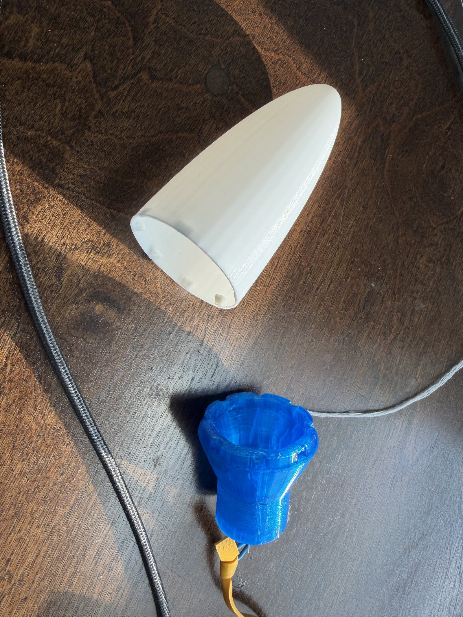
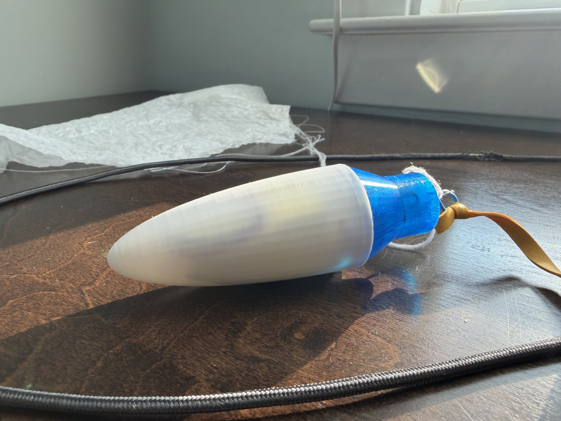
White PLA cone, blue TPU base adapter, shock cord and shroud lines. Shown apart and integrated — with the flight computer inside, the whole nose lifts away as one unit at ejection and comes down under the parachute.

  • Cone — white PLA, printed hollow
  • Adapter — blue TPU, flexible friction coupler
  • Tie-in — elastic shock cord + parachute lines at the adapter
Nose cone and blue TPU adapter separated
Exploded — cone / adapter
Nose cone assembled onto blue adapter with parachute behind
Integrated — with parachute

Flight computer

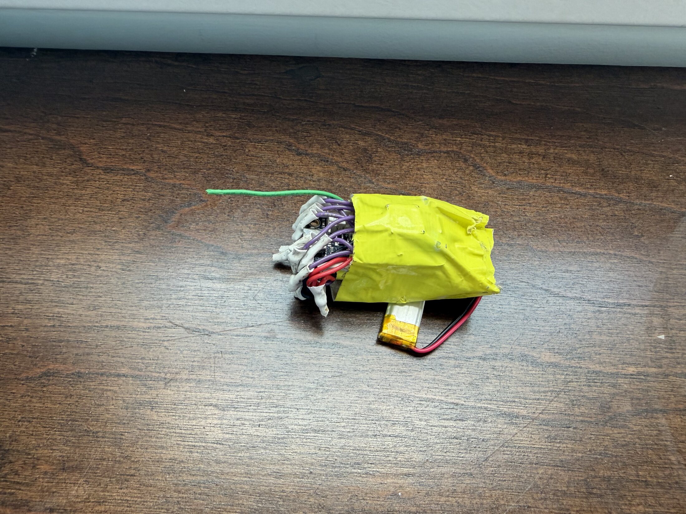
An RP2040 carrying barometer, altimeter, gyro and GPS, wrapped in Kapton and flown on a single LiPo. This is Mark-I hardware, unchanged — the point of Mark-II was to improve the structure around a known-good avionics stack, not to debug two things at once.

  • MCU — RP2040
  • Sensing — barometric pressure, altitude, 6DOF gyro/accel, GPS
  • Link — wireless downlink to the ground station, logged live
  • Power — single LiPo cell
RP2040 payload electronics wrapped in Kapton tape with LiPo battery
Payload stack — as flown

Airframe & fins

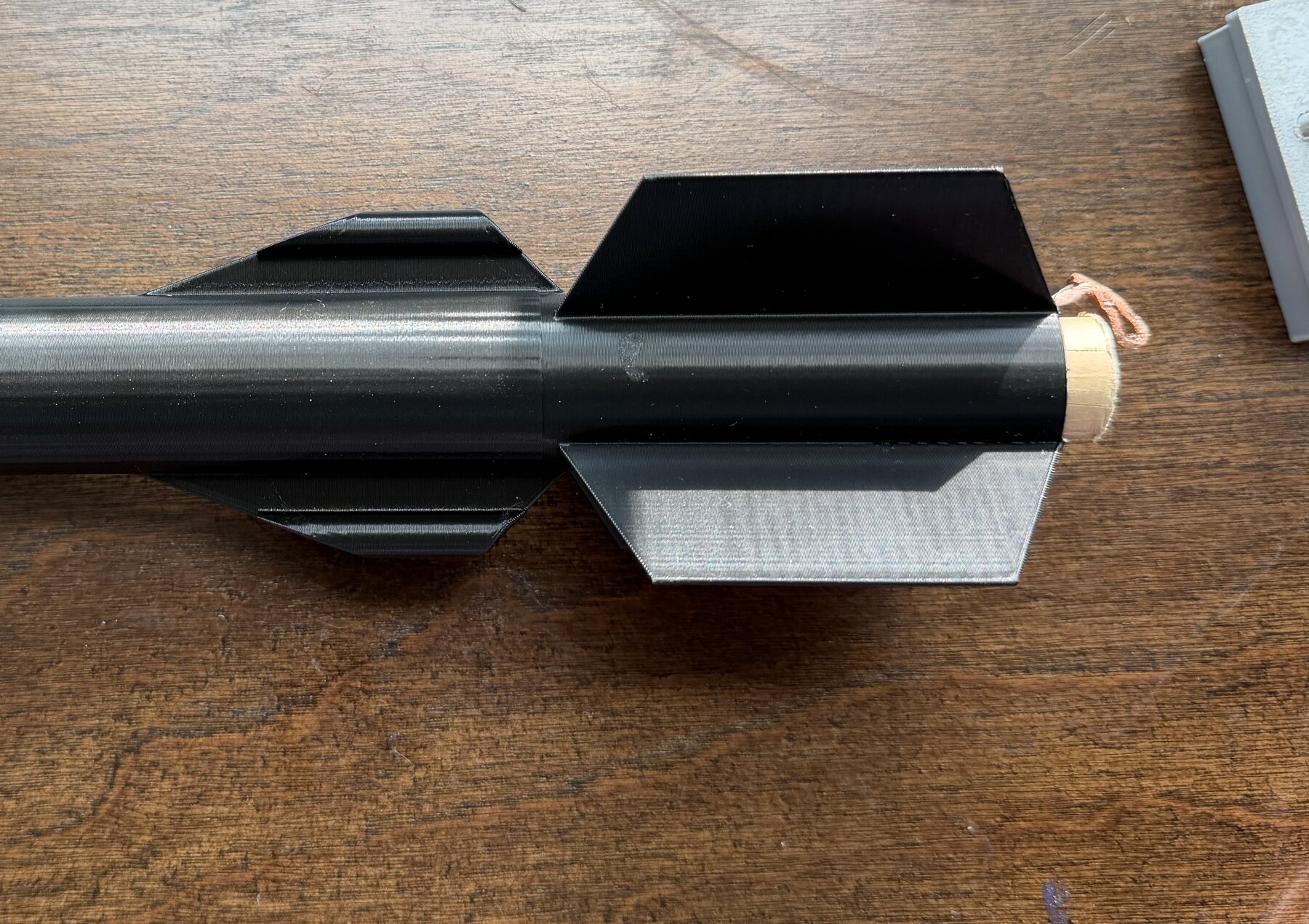
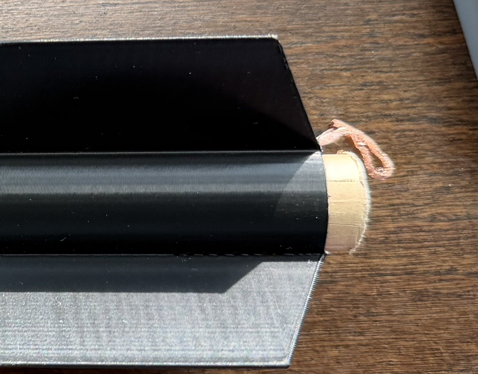
Black PLA. The fins come off the printer attached to the body — no gluing, no alignment jig, no added mass at the joint. Mark-I needed each fin bonded on after the fact, which is where both the weight and the length went.

  • Material — black PLA
  • Fins — printed integral to the body tube
  • Result — ~40 g lighter and ~50 mm shorter than Mark-I
Aft section of the Mark-II body showing fins printed as part of the tube
Aft section — fins integral to the print

Motor mount

The one place copper shows up. A small tab set into the base bends in just enough to catch the motor and hold it there, while staying out of the way of the burn. Ejection pressure can then only go forward, into the payload and parachute. The motor is the single component on this vehicle that wasn't made in house.

  • Retention — small copper tab set into the base
  • Clearance — bent in only as far as it needs to be, clear of the blast
  • Fixes — motor backing out of the mount during ejection
Aft end of the rocket showing the motor casing and copper retention clip
Copper tab at the aft end

Ground segment

Ground station

Printed grey enclosure

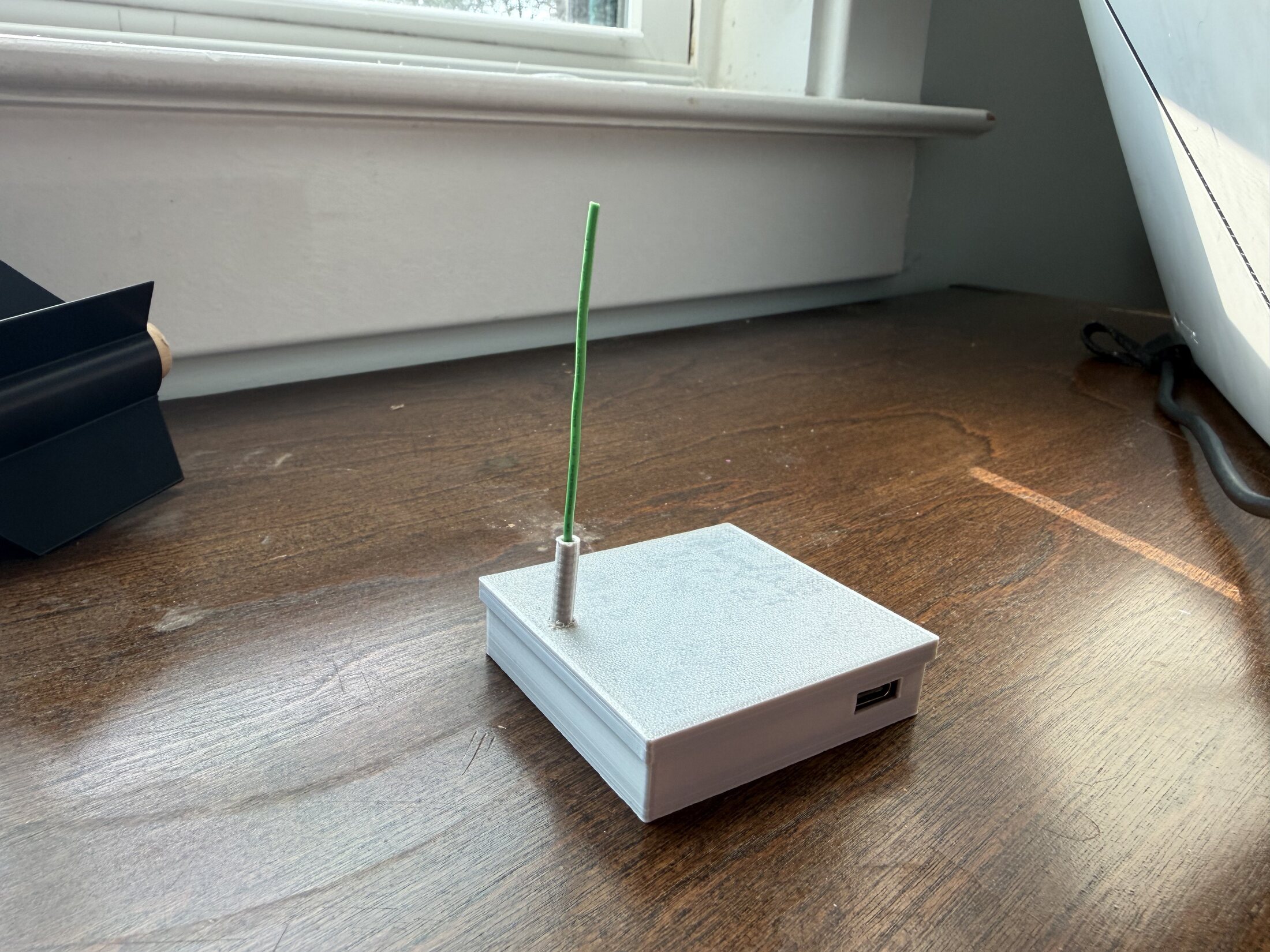
The receiver is Mark-I electronics in a new printed grey enclosure: a flat, low box with a moulded-in antenna mast and a single USB port to the laptop. It sits on the ground at the pad, holds the link through the whole flight, and hands every packet to the ground station software.

  • Enclosure — 3D-printed grey, new for Mark-II
  • Radio — Mark-I ground electronics, reused
  • Interface — USB to the laptop running the ground station software
Grey 3D-printed ground station enclosure with vertical antenna
Ground station — printed enclosure, mast antenna

Ground software

Rocket Ground Station

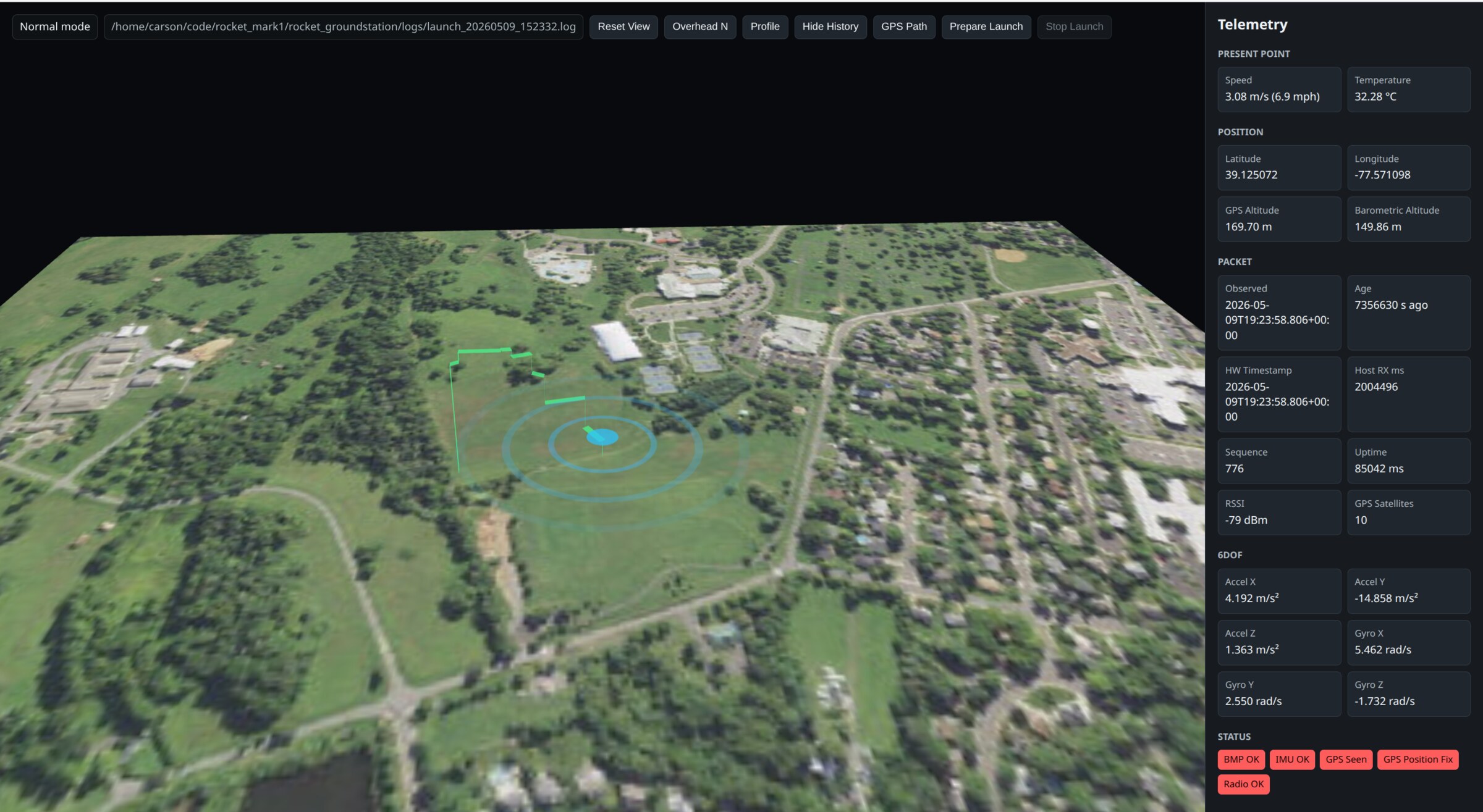
Custom ground monitoring software. It listens to the wireless downlink, draws the vehicle's position on 3D terrain, and writes every packet to a launch log — the whole flight path plus altitude, pressure, GPS and link metrics, as received.

BMP OKIMU OKGPS SeenGPS Position FixRadio OK
Rocket Ground Station — telemetry map
Rocket Ground Station software: 3D terrain map with flight path and a live telemetry panel
Flight path
Live 3D track over terrain imagery, with overhead and profile views, GPS path overlay and full history replay from the log.
Present point
Speed, temperature, latitude / longitude, GPS altitude and barometric altitude for the current packet.
6DOF
Accelerometer and gyro on all three axes, straight off the payload IMU.
Link health
RSSI, satellite count, packet sequence, packet age, hardware timestamp and uptime — so a data gap is never ambiguous.
Launch logging
Every launch writes a timestamped .log that can be reloaded and re-flown afterwards.
Pad control
Prepare Launch / Stop Launch arm and close out a session from the same window.
Status board
Barometer, IMU, GPS fix and radio each report their own health before the vehicle leaves the pad.
Runs local
Served on the laptop at the pad — no internet needed in the field.

Flight test

Launch videos

Mark-II footage goes here as it is flown — pad camera, onboard telemetry replay, and recovery.

Drop clips into assets/video/ and add them to the FLIGHTS list at the bottom of index.html — each entry becomes a player in this grid.

Revision

Mark-I → Mark-II

ItemMark-IMark-II
Fins Separate parts, glued to the tube Printed as part of the bodyNo glued joints
Dry mass Baseline About 40 g lighter−40 g
Length Baseline About 50 mm shorter−50 mm
Motor retention None — motor could back out during ejection Copper tab set into the baseFailure mode closed
Flight electronics RP2040 avionics stack Same stack, carried overUnchanged on purpose
Ground electronics Mark-I receiver Same receiver, new printed grey enclosure
Sourcing Scratch-built Scratch-built — everything except the motor